Dislocation Dynamics - Working Notes (2006/06/19)
LSMDD: Development Notes
This document records the current status and issues in the development of the parallel dislocation dynamics simulation.
2006 June 19
I have been testing the code by trying to reproduce Xiang Yang's results from the 2003 paper. Most of the results are in good agreement when run at the same resolution as in the paper (64x64x64). Unfortunately, at higher resolutions, stability issues seem to arise for some of the examples.Main Issues
- Maximum stable dt as a function of dx.
- The maximum angle allowed between the Burgers vector and the tangent vector to the dislocation line for a dislocation line segment to be considered to have pure screw character.
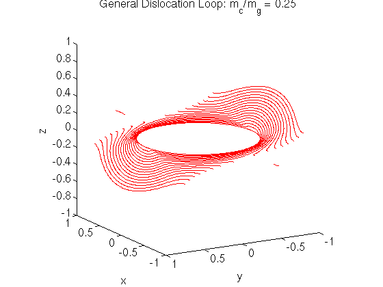
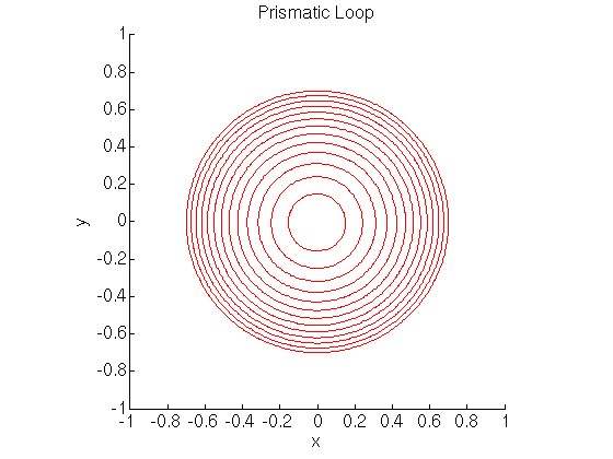
Dislocation loops
At a resolution of 64x64x64, agreement is with Xiang Yang's results are good for the prismatic, glide and general dislocation loop examples.
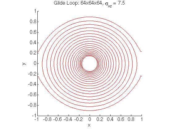
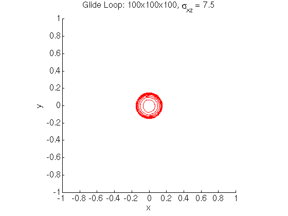
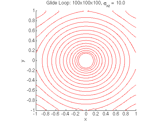
At a resolution of 100x100x100, the glide loop example required a larger applied stress to overcome the tendency for the loop to shrink. This makes sense in light of the fact that the core radius is smaller at higher resolutions.
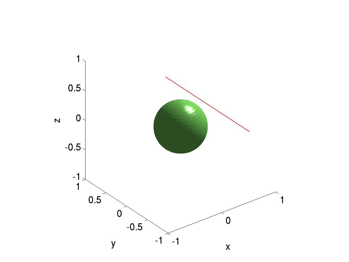
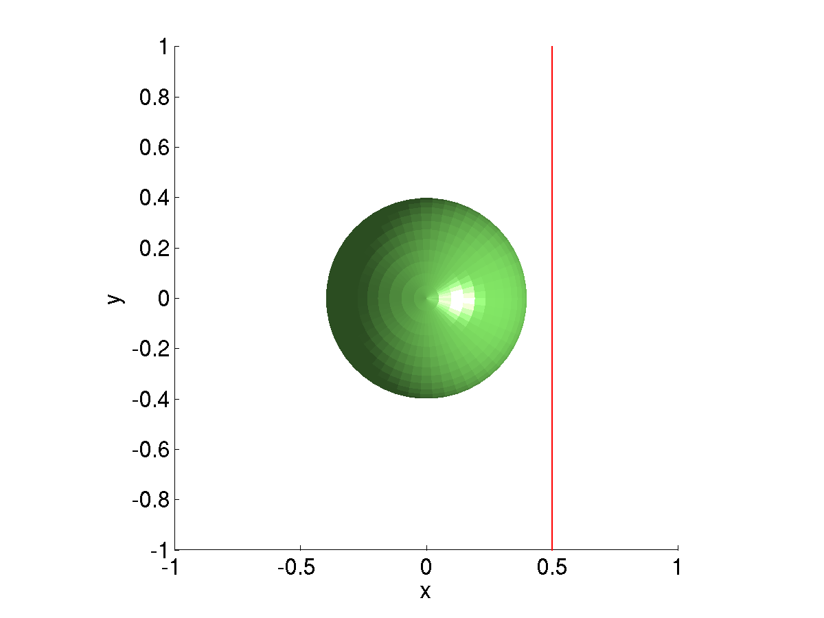
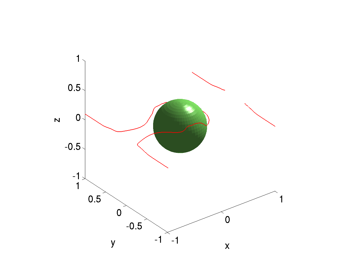
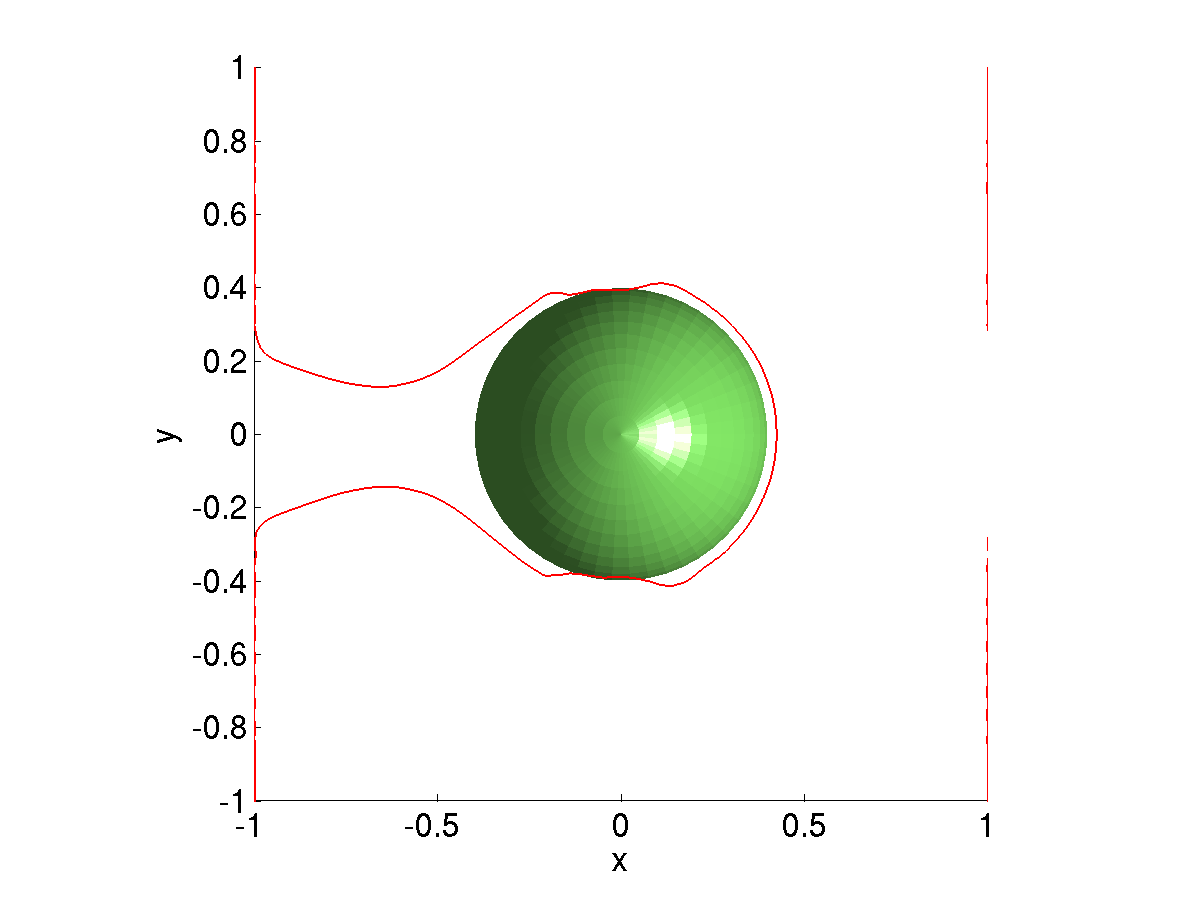
Dislocations bypassing particles
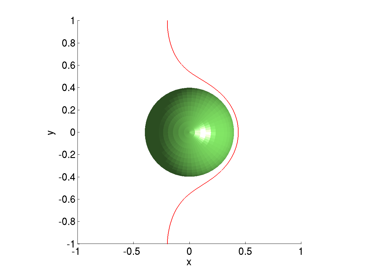
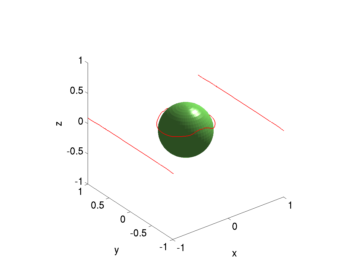
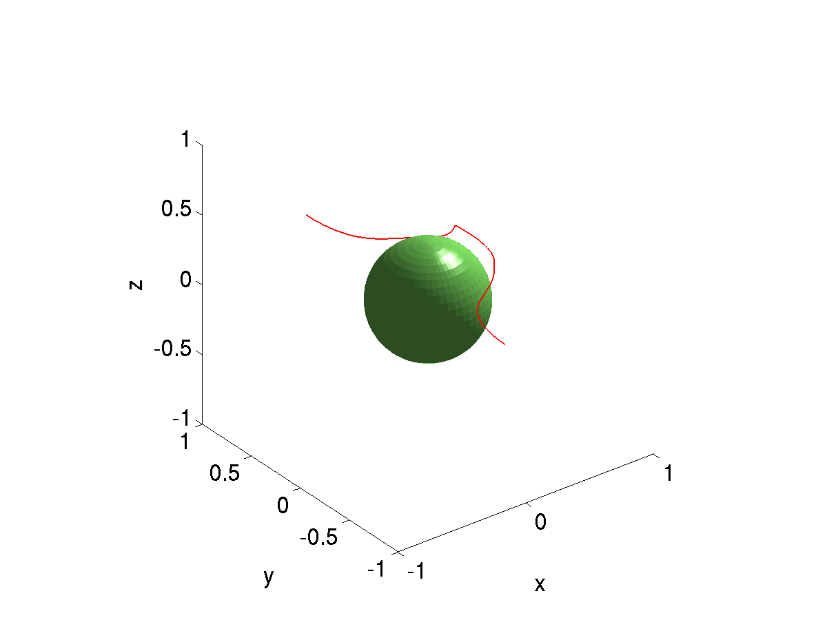
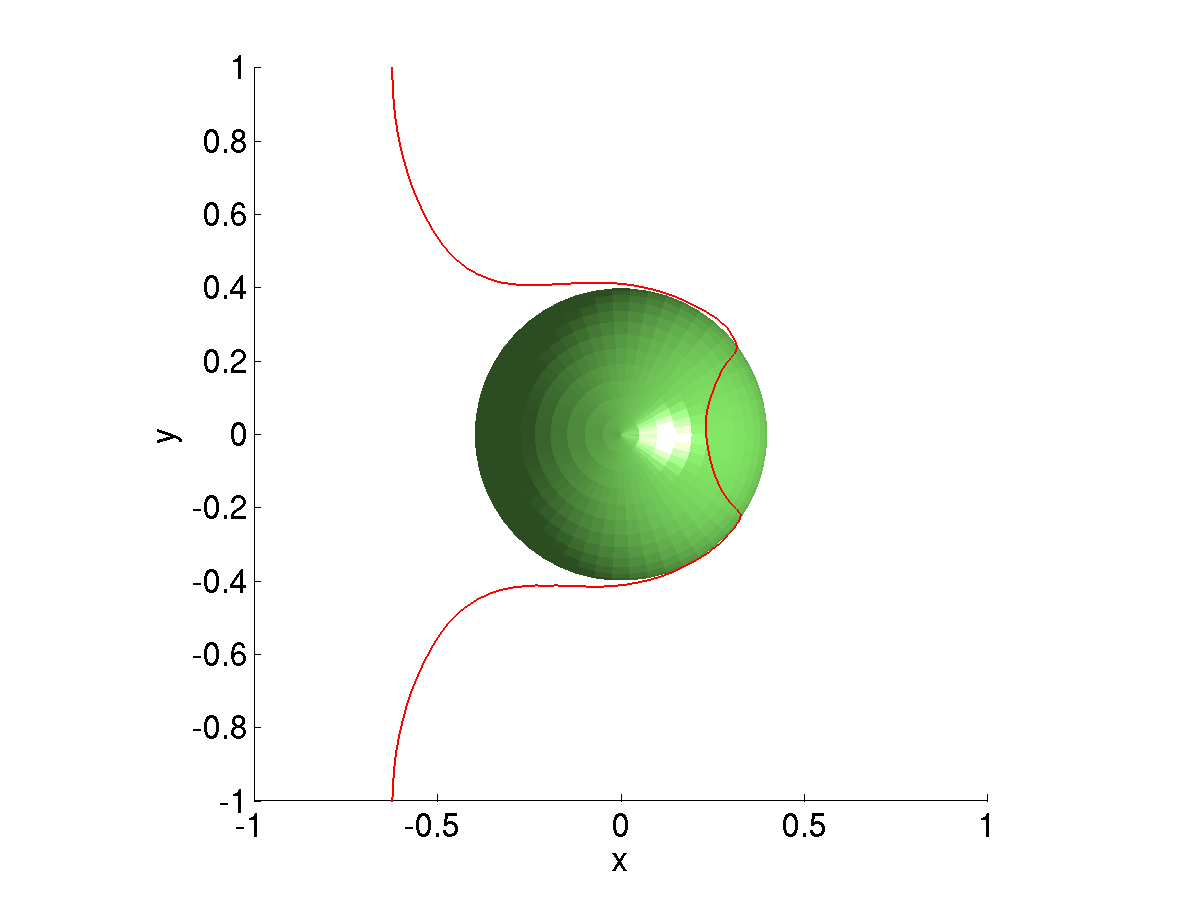
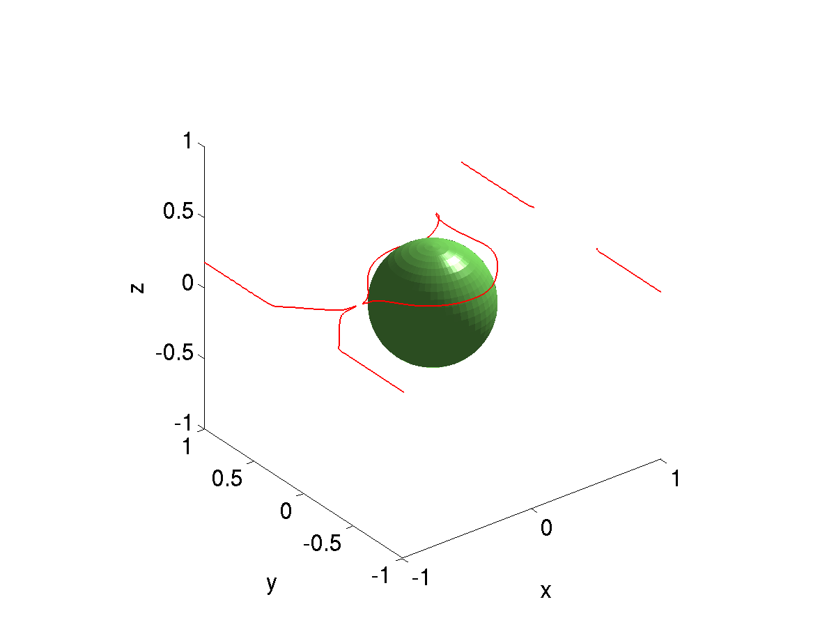
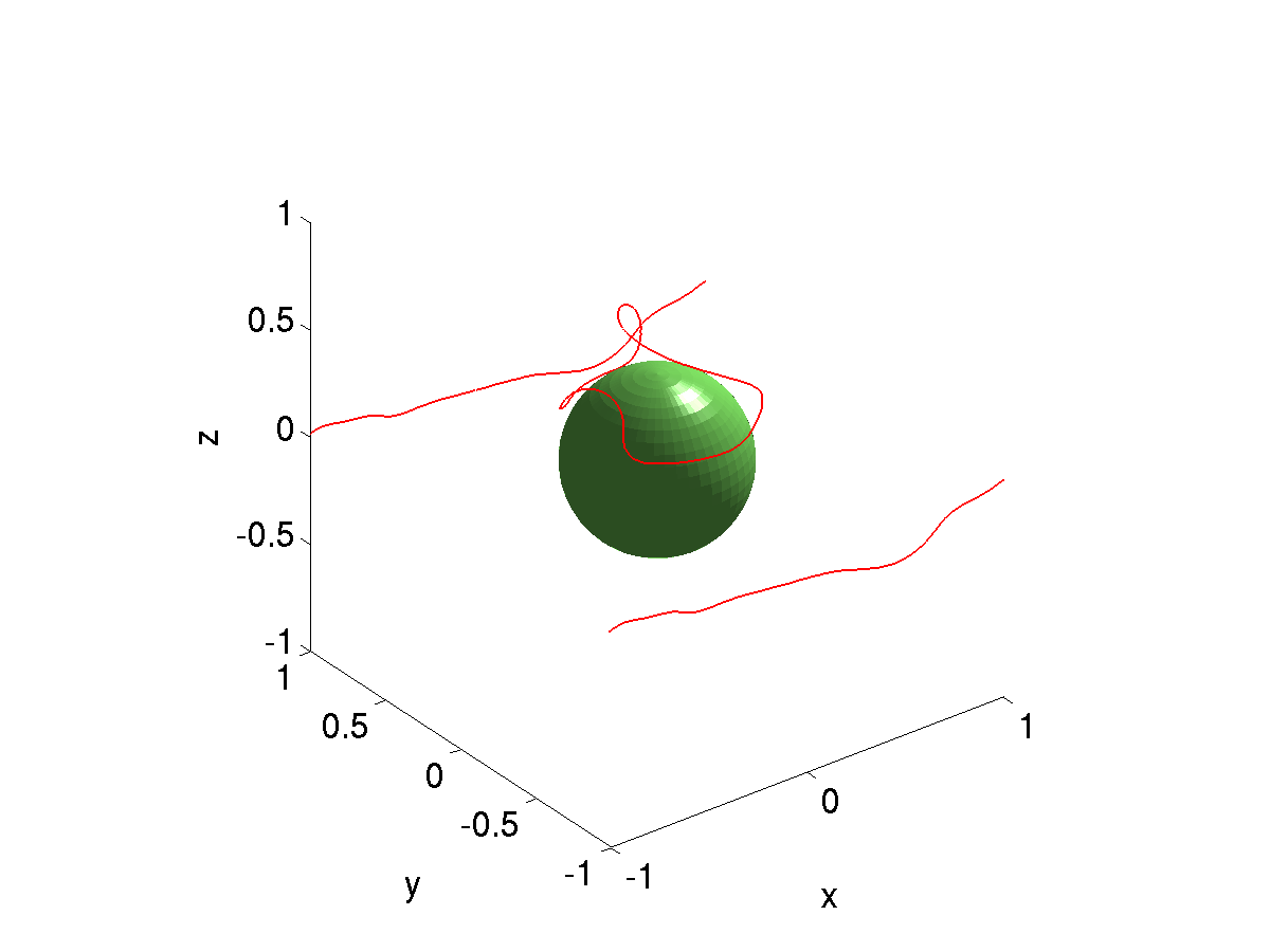
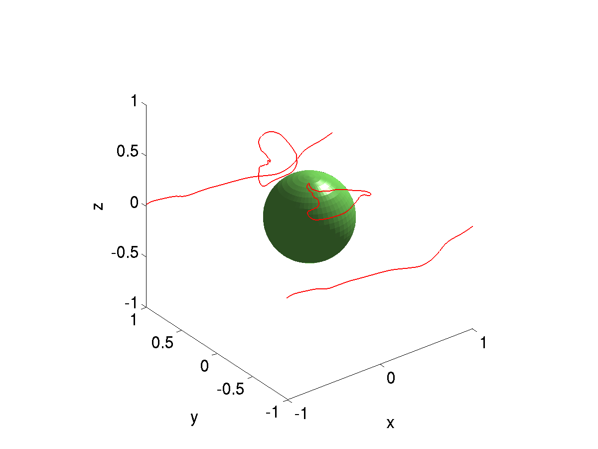
At a resolution of 64x64x64, I get reasonable agreement with the serial code at short times, but at longer times, the results are not in complete agreement. The main difference seems to be that portions of the dislocation line that are pure screw do not cross-slip as much in the parallel code as in the serial code. I am currently discussing with Xiang Yang what the appropriate criteria should be for considering a dislocation line segment to have pure screw character.Cross-slip (64x64x64)
As you can see in the following figures, the dislocation line does not cross slip on the sides of the particle as much as they did in Xiang Yang's simulations.The maximum angle allowed between the Burgers vector and the tangent vector to the dislocation line for a dislocation line segment to be considered to have pure screw character is approximately 3 times the grid spacing.
|
|

|

|

|

|
|
|

|

|
Cross-slip (100x100x100)
At higher grid resolutions, the dislocation line is more unstable than for the 64x64x64 grid and there is less cross-slip for the portions of the dislocation line on the two sides of the obstacle.The maximum angle allowed between the Burgers vector and the tangent vector to the dislocation line for a dislocation line segment to be considered to have pure screw character is approximately 3 times the grid spacing.

|

|

|
|

|

|

|

|
|

|
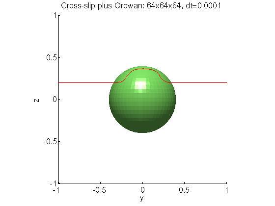
Cross-slip plus Orowan (64x64x64)
As you can see in the following figures, the dislocation line does not cross slip up backside of the particle as much as they did in Xiang Yang's simulations.The maximum angle allowed between the Burgers vector and the tangent vector to the dislocation line for a dislocation line segment to be considered to have pure screw character is approximately 3 times the grid spacing.

|

|
|

|

|
|
|

|
|

|
|

|
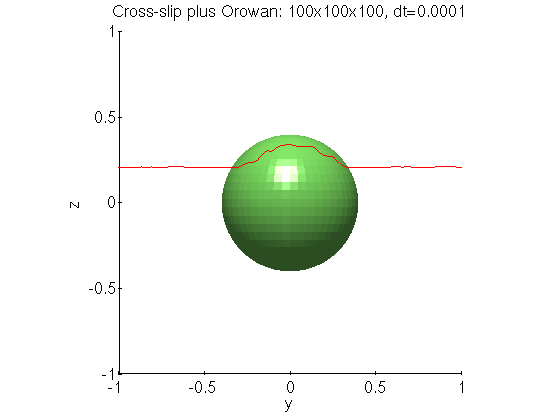
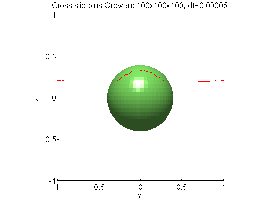
Cross-slip plus Orowan (100x100x100)
At higher grid resolutions, we require smaller time step size to get a stable dislocation line. But even with the smaller dt, the dislocation line does not cross-slip as high as in the 64x64x64 resolution case. One other potential issue is the lack of symmetry in the result when using a grid of size 100x100x100.The maximum angle allowed between the Burgers vector and the tangent vector to the dislocation line for a dislocation line segment to be considered to have pure screw character is approximately 3 times the grid spacing.

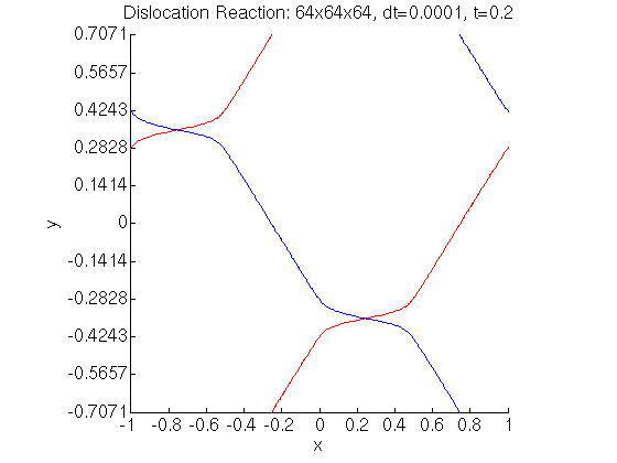
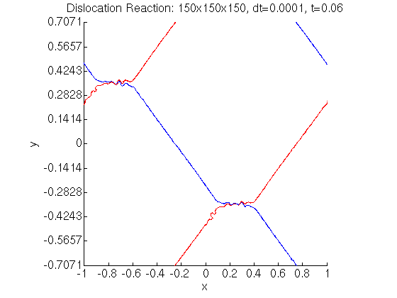
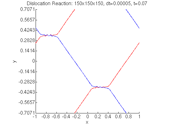
Dislocation Reactions
I tested the dislocation reaction example where two sets of initially straight dislocation lines react to form a hexagonal-like structure. At a resolution of 64x64x64, the reaction does not complete and a large gap remains between the edges of the crossing dislocation lines. At high resolutions, some sort of instability occurs near the region where the dislocations cross.The maximum angle allowed between the Burgers vector and the tangent vector to the dislocation line for a dislocation line segment to be considered to have pure screw character is approximately 3 times the grid spacing.