Dislocation Dynamics - Working Notes (2007/08/22)
Effects of Numerical Core Size on Dislocation Stress Fields
Use of finite sized dislocation cores (i.e. smearing) in numerical calculations causes deviations in the stress fields on the order of the square of the numerical core radius. This deviation is negligible far from the dislocation core but causes significant errors in the stress fields near the dislocation core. While using a smaller dislocation core size reduces the magnitude of the error throughout the entire stress field, using the numerical core size as the physical core size actually leads to errors near the dislocation core that increase as the size of the numerical core is decreased (even with the use of finer grids). The following results show the effects of the numerical core on the error in the stress fields outside of the numerical and physical dislocation core.
One of the motivations for investigating these errors further is that they result in spurious forces between dislocation lines when they are near each other. For instance, we have seen a nonzero force that should be exactly zero (shown analytically) that leads to drift in a dislocation model of a grain boundary. These spurious forces also cause an apparent repulsive force between dislocations that should physically react to form a single dislocation.
For all of the results, the dislocation configuration is taken to be an array of edge dislocations with Burgers vector in the (1,0,0) direction and line direction in the (0,0,1) direction. The array ordered such that the normal to the plane of the dislocation array is in the (1,0,0) direction. The dislocation array is periodically repeated in the x-direction. The simulation cells is [-50,50]x[-40,40], which implies that the inter-dislocation spacing is 80 and the distance between periodic images of the dislocation array is 100.
NOTES:
- All calculations are on a uniform grid with dx = dy using the Fourier transform formulation in Xiang et. al.
- The errors for the stress fields are only computed OUTSIDE of the specified physical core.
- Larger versions of all figures on this page are available by clicking on them.
- Code used to obtain these results are: smeared_core_effects.m, results.m sigma_D.m
Effect of Grid Resolution
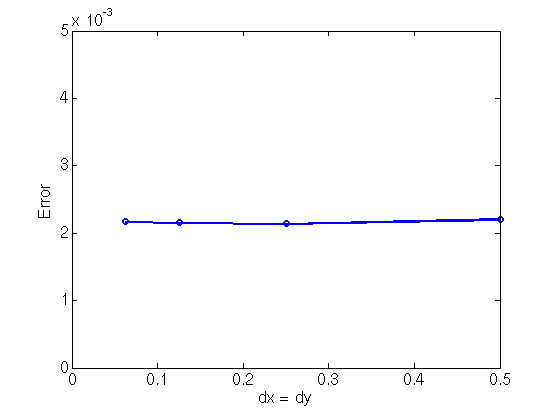
Refining the grid does not reduce the error. Once the grid resolution is fine enough (does not need to be that fine thanks to the accuracy of the FFT), the error in the stress is dominated by error caused by using a smeared core.| Error in stress field outside the dislocation core is independent of grid resolution. The physical and numerical core radii are fixed at 4 and 1, respectively. |
|
Dependence of Error on Numerical Core Size
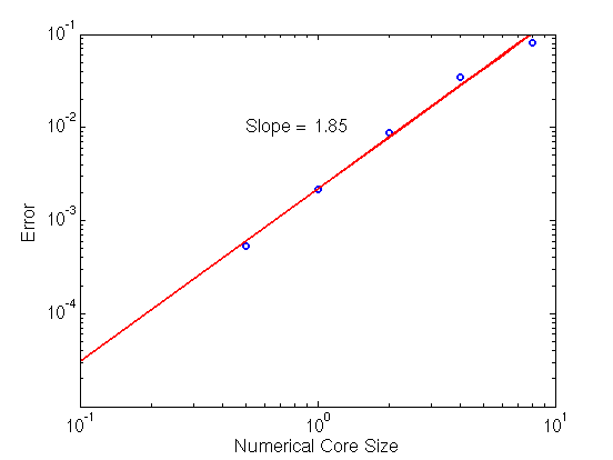
The error caused by the finite core scales as the square of the numerical core radius. We can intuitively understand the scaling of this error by considering the representation of a single edge dislocation as a decomposition of two dislocations each with half of the Burgers vector of the original dislocation and separated by a distance equal to the core radius. Using the perturbed positions of the two dislocations in the formulas for the stress fields results in a leading order deviation of the stress field at any position space that is on the order of the core radius squared.| Error shows a roughly quadratic dependence on the numerical core radius. Here the physical core radius is fixed at 4 and the grid resolution is fixed at 0.25. |
|
Increasing Error when Physical Core and Numerical Core are Equal
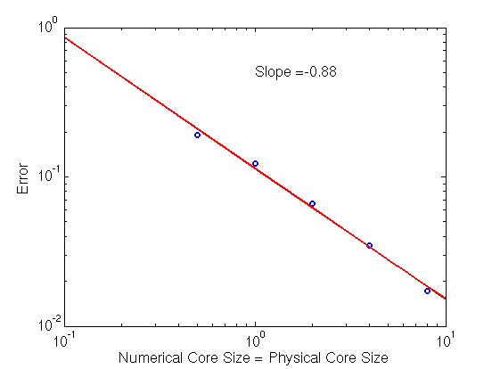
The choice of taking the physical core size to be the same as the numerical core size leads to an error in the stress fields around the dislocation core that increases with decreasing core size.| Error shows a roughly inverse dependence on the numerical core radius. Here the grid resolution is fixed at 0.25. |
|
Improved Accuracy Near Core Using Higher-order Smoothed Delta Functions
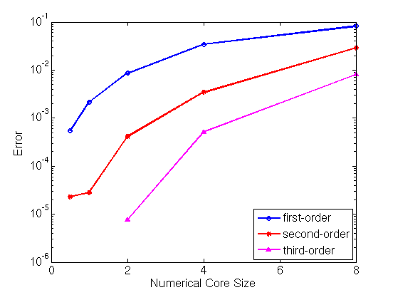
Higher-order smoothed delta functions can be used decrease the error caused by the smeared core. They decrease the error by concentrating the distribution of the smeared core near the true position of the dislocation core. However, a larger number of grid points are required to resolve the numerical core when higher-order smoothed delta functions are used. Second-order delta functions seem to give a reasonable compromise between accuracy in the stress fields and the grid spacing required to resolve the numerical core.- First-order smoothed delta functions require ~6 grid cells within the dislocation core (core radius = 3 grid cells) to eliminate inaccuracies due to grid resolution.
- Second-order smoothed delta functions require ~8-12 grid cells within the dislocation core (core radius = 4-6 grid cells) to eliminate inaccuracies due to grid resolution.
- Third-order smoothed delta functions require ~24-48 grid cells within the dislocation core (core radius = 12-24 grid cells) to eliminate inaccuracies due to grid resolution.
The following results were obtained on a grid with dx = dy = 0.125 for first- and second-order smoothed delta functions and dx = dy = 0.041667 for the third-order smoothed delta function to remove grid resolution inaccuracies.
| Comparison of the error for first-, second-, and third-order smoothed delta functions as a function of numerical core size. Here the physical core radius is fixed at 4. |
|
Summary/Conclusions
When doing dislocation dynamics simulations, the stress field calculations should use a numerical core that is many times smaller than the desired physical core. Based on these computational experiments with a physical core radius on the order of a few times the Burgers vector and when using the first-order smoothed delta function to smear the core, the numerical core should be about 10 times smaller for the error in the stress fields to be on the order of 1e-4. When the second-order smoothed delta function is used, the numerical core can be taken to be larger (on the order of 2 to 4 times smaller than physical core) to achieve the same accuracy.Based on the results of these computational experiments, we should be using second-order smoothed delta functions with a numerical core that is about 2 to 4 times smaller than the physical core radius. This implies the use of a grid resolution that places at least 10-20 grid points within the radius of the desired physical dislocation core.